increased are furthermore
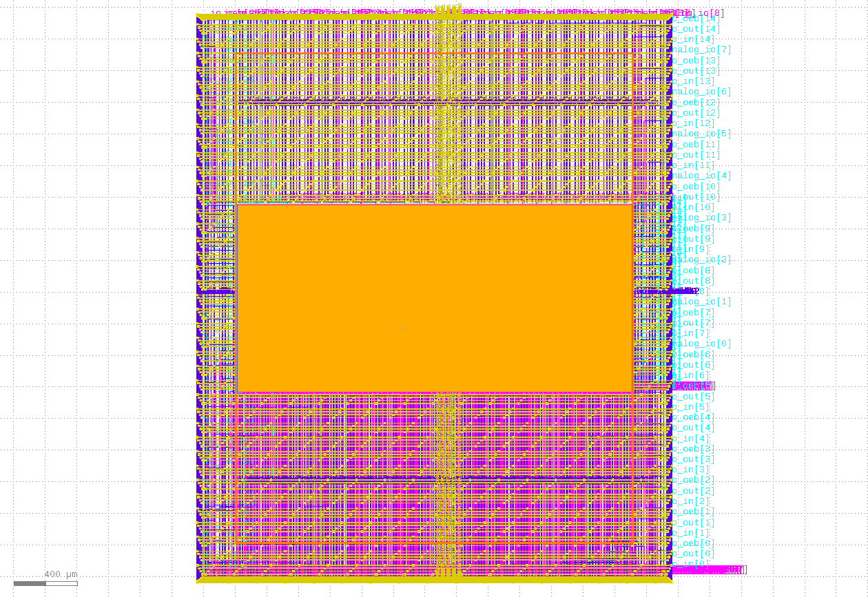
This project contains 4 PWM modules that can be set through the Wishbone bus. Each of them can be configured independently. The four outputs can be observed through both GPIO and Logic Analyzer. The project can be used to control the driver of the hobby cars. The layout of the project can be seen below.
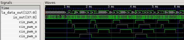
There are three different operating modes: standard mode, blink mode, and heartbeat mode. In the standard mode, the output signal gives a periodic PWM signal with the same period and duty cycle. In the blink mode, the output toggles between two different PWM signals with a fixed period and duty cycle. In the heartbeat mode, there are again two different PWM signals. But there is a gradual transition between them. The signals can be seen below from the Icarus Verilog.
There are 16 registers for each PWM module. The register map can be found in verilog/dv/register_map.h in the GitHub repo. The registers are as follows:
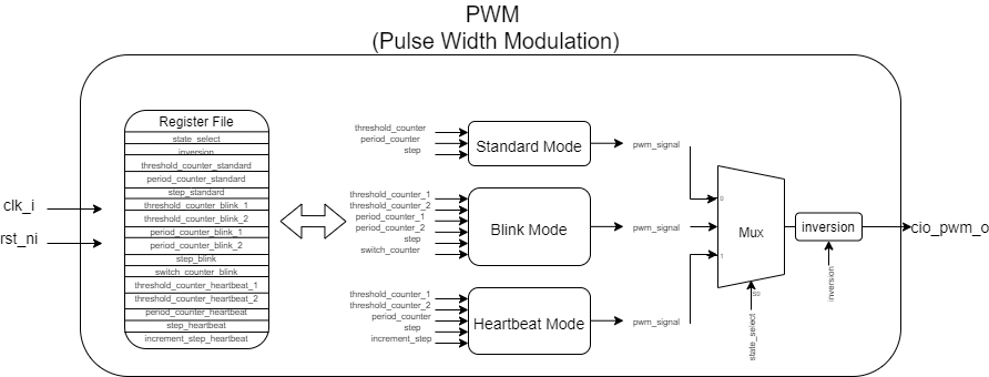
state_select:                  The operating mode of the PWM is chosen.
inversion:                     The output is inverted or not.
threshold_counter_standard:    Counter value that determines "1" time of the PWM signal for the standard mode.
period_counter_standard:       Counter value that determines the total period of the PWM signal for the standard mode.
step_standard:                 The counter increases by step times at a cycle.
threshold_counter_blink_1:     Counter value that determines "1" time of the first PWM signal for the blink mode.
threshold_counter_blink_2:     Counter value that determines "1" time of the second PWM signal for the blink mode.
period_counter_blink_1:        Counter value that determines the total period of the first PWM signal for the blink mode.
period_counter_blink_2:        Counter value that determines the total period of the second PWM signal for the blink mode.
step_blink:                    The counter increases by step times at a cycle.
switch_counter_blink:          How fast the toggle between two PWM signals occurs are configured with this value.
threshold_counter_heartbeat_1: Counter value that determines "1" time of the first PWM signal for the heartbeat mode.
threshold_counter_heartbeat_2: Counter value that determines "1" time of the first PWM signal for the heartbeat mode.
period_counter_heartbeat:      Counter value that determines the total period of the PWM signal for the heartbeat mode.
step_heartbeat:                The counter increases by step times at a cycle.
increment_step_heartbeat:      How fast the gradual change between two PWM signals occurs are configured with this value.
The diagram of a PWM module can be seen below.
The project was simulated at the RTL stage with the Caravel. It is DRC & LVS clean. There are no setup, hold, slew, max capacitance, max fanout violations at the typical case. The hardened macro has an area of 2.3 um x 1 um. The area was increased substantially to allow routability.