| # General Purpose Bandgap Reference Circuit - avsdbgp_3v3_sky130_v2 |
| |
| A Bandgap Reference is an analog circuit, which is used to provide a constant output reference voltage being independent of Temperature, Process and Supply voltage variations. The analog IP **avsdbgp_3v3** is a General Purpose Bandgap Reference ciruit, which is designed using **Sky130nm** technology in this project. |
| |
| For detailed information regarding the Bandgap Reference circuit click [here](https://github.com/vsdip/avsdbgp_3v3_sky130_v2/blob/main/Documents/General_purpose_BGR.pdf). The Design specifications provided for avsdbgp_3v3 can be found [here](https://github.com/vsdip/avsdbgp_3v3_sky130_v2/blob/main/Documents/Specifications.pdf). |
| |
| <p> </p> |
| |
| # Table of Contents |
| * Performance parameters Bandgap Reference IP |
| |
| * Circuit Implementation of Bandgap Reference IP |
| |
| - Block Diagram of Bandgap Reference IP |
| - Schematic of Bandgap Reference IP |
| * Downloading the files on your System |
| * Pre-Layout Simulation of Bandgap Reference IP circuit using Ngspice |
| - Ngspice |
| - Pre-Layout Simulation plots of Bandgap Reference IP circuit |
| - Vbgp v/s Temperature [ -40C - 140C] @ RL = 100M ohms plot |
| - Vbgp v/s VDD [ 2V - 4V] @ RL = 100M ohms plot |
| - Temperature Coefficient of Vbgp v/s Temperature [ -40C - 140C] @ RL = 100M ohms plot |
| - Voltage Coefficient of Vbgp v/s VDD [ 2V - 4V] @ RL = 100M ohms plot |
| - Start-Up Time of Vbgp @ RL = 100M ohms plot |
| - On-Off-Current of Vbgp wrt Enable @ RL = 100M ohms plot |
| * BGR Layout |
| - Magic |
| - Layout |
| * Post-Layout Simulation of Bandgap Reference IP circuit using Ngspice |
| - Vbgp v/s Temperature [ -40C - 140C] @ RL = 100M ohms plot |
| - Vbgp v/s VDD [ 2V - 4V] @ RL = 100M ohms plot |
| - Temperature Coefficient of Vbgp v/s Temperature [ -40C - 140C] @ RL = 100M ohms plot |
| - Voltage Coefficient of Vbgp v/s VDD [ 2V - 4V] @ RL = 100M ohms plot |
| - Start-Up Time of Vbgp @ RL = 100M ohms plot |
| - On-Off-Current of Vbgp wrt Enable @ RL = 100M ohms plot |
| |
| |
| <p> </p> |
| |
| # Performance parameters of Bandgap Reference IP |
| <p> </p> |
| |
| | Parameter | Description | Min | Type | Max | Unit | Condition | |
| | :----: | :----: | :----: | :----: | :----: | :----: | :----: | |
| | VBGP | Output reference voltage | 1.19490 | 1.19756 | 1.19764 | Volt | T= -40 to 140C, VDD=3.3V | |
| | VBGP | Output reference voltage | 1.11400 | 1.19756 | 1.21933 | Volt | VDD=2V to VDD=4V, T=27C | |
| | VDD | Supply Voltage | | 3.3 | | Volt | T=-40C to 125C| |
| | IDD | Supply Current | | 21.9636 | | uA | EN=1 | |
| | IDD | Supply Current | | 24.4 | | pA | EN=0 | |
| | RL | Load Resistance | | 100 | | Mohm |VDD=3.3V, T=27C| |
| <p> </p> |
| |
| # Circuit Implementation of Bandgap Reference IP |
| ## Block Diagram of Bandgap Reference IP |
|  |
| |
| ## Schematic of Bandgap Reference IP |
| <p> </p> |
| |
|  |
| <p> </p> |
| |
| # Downloading the files on your System |
| <p> </p> |
| |
| The files from this repository can be downloaded and used by the following commands :- |
| >`sudo apt install -y git` |
| |
| >`git clone https://github.com/vsdip/avsdbgp_3v3_sky130_v2.git` |
| <p> </p> |
| |
| # Pre-Layout Simulation of Bandgap Reference IP circuit |
| |
| The circuit implementation of Bandgap reference IP **avsdbgp_3v3** is simulated using Ngspice to analyse its performance according to the Design Specifications provided. |
| <p> </p> |
| |
| ## Ngspice |
| <p> </p> |
| Ngspice is an open source mixed-signal circuit simulator. To install Ngspice on Ubuntu, open terminal window and type :- |
| |
| >`sudo apt-get install -y ngspice` |
| |
| After successful installation, to invoke Ngspice type the following command on the terminal window. |
| >`ngspice <circuit file to be simulated>` |
| |
| <p> </p> |
| |
| |
| |
| ## Pre- Layout Simulation plots of Bandgap Reference IP circuit |
| <p> </p> |
| |
| |
| To simulate the files for Pre- Layout simulations |
| <p> </p> |
| |
| >`cd avsdbgp_3v3_sky130_v2/Pre_Layout_Simulations/Circuits/` |
| <p> </p> |
| |
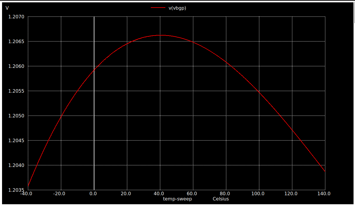
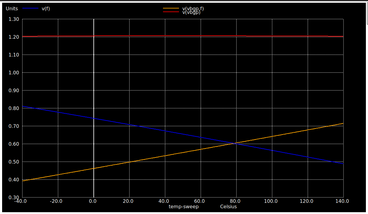
| ## Vbgp v/s Temperature [ -40C - 140C] @ RL = 100M ohms plot |
| <p> </p> |
| To observe the effect of temperature on the circuit, the temperature is varied from -40C to 140C. On the terminal window, type :- |
| <p> </p> |
| |
| >`ngspice temp_avsdbgp_3v3.cir` |
| <p> </p> |
| The output plot as obtained can be seen below :- |
| |
| <p> </p> |
| |
|  |
| <p> </p> |
| |
| |
|  |
| <p> </p> |
| |
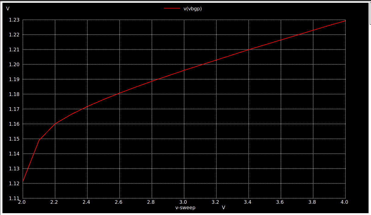
| ## Vbgp v/s VDD [ 2V - 4V] @ RL = 100M ohms plot |
| <p> </p> |
| To observe the effect of Supply voltage on the circuit, the temperature is varied from 2V to 4V. On the terminal window, type :- |
| <p> </p> |
| |
| >`ngspice vdd_variation_avsdbgp_3v3.cir` |
| <p> </p> |
| The output plot as obtained can be seen below :- |
| <p> </p> |
| |
|  |
| <p> </p> |
| |
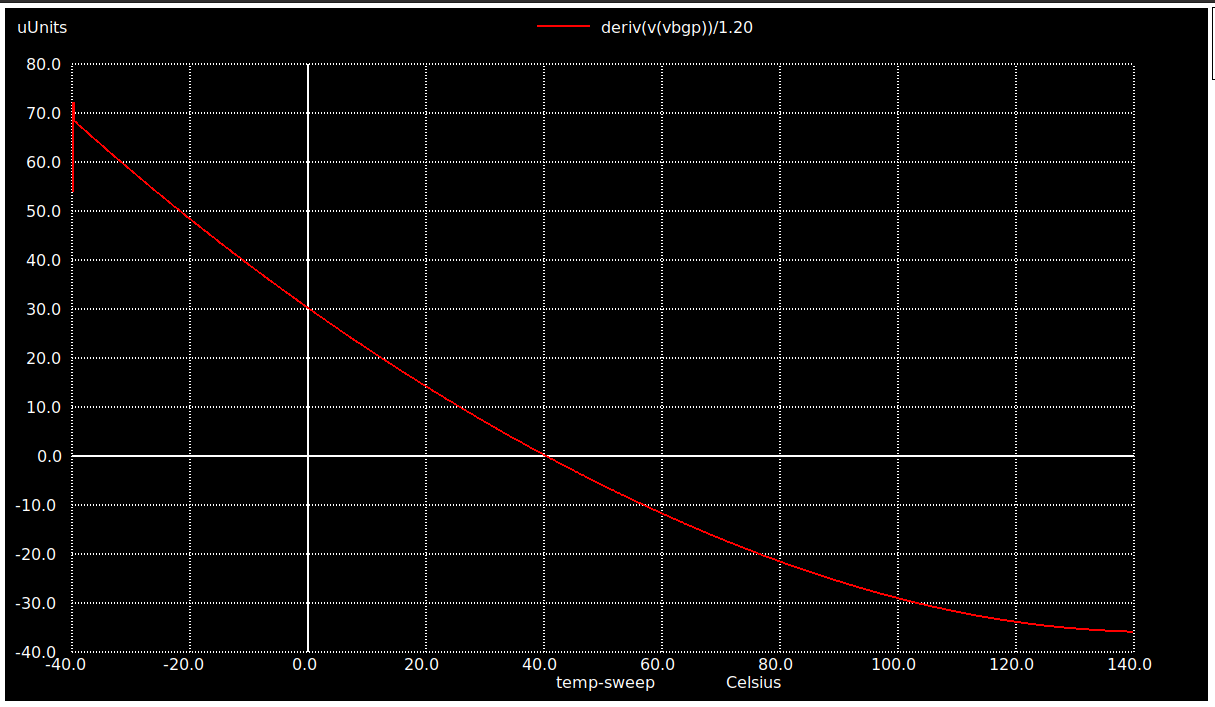
| ## Temperature Coefficient of Vbgp v/s Temperature [ -40C - 140C] @ RL = 100M ohms plot |
| <p> </p> |
| On the terminal window, type :- |
| <p> </p> |
| |
| >`ngspice Temp_coeff_avsdbgp_3v3.cir` |
| <p> </p> |
| The output plot as obtained can be seen below :- |
| <p> </p> |
| |
|  |
| <p> </p> |
| |
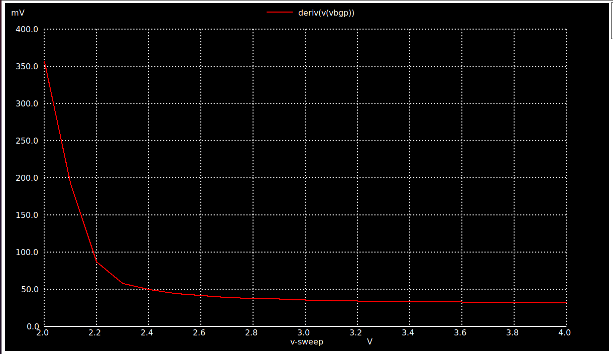
| ## Voltage Coefficient of Vbgp v/s VDD [ 2V - 4V] @ RL = 100M ohms plot |
| <p> </p> |
| On the terminal window, type :- |
| <p> </p> |
| |
| >`ngspice voltage_coeff_avsdbgp_3v3.cir` |
| <p> </p> |
| The output plot as obtained can be seen below :- |
| <p> </p> |
| |
|  |
| <p> </p> |
| |
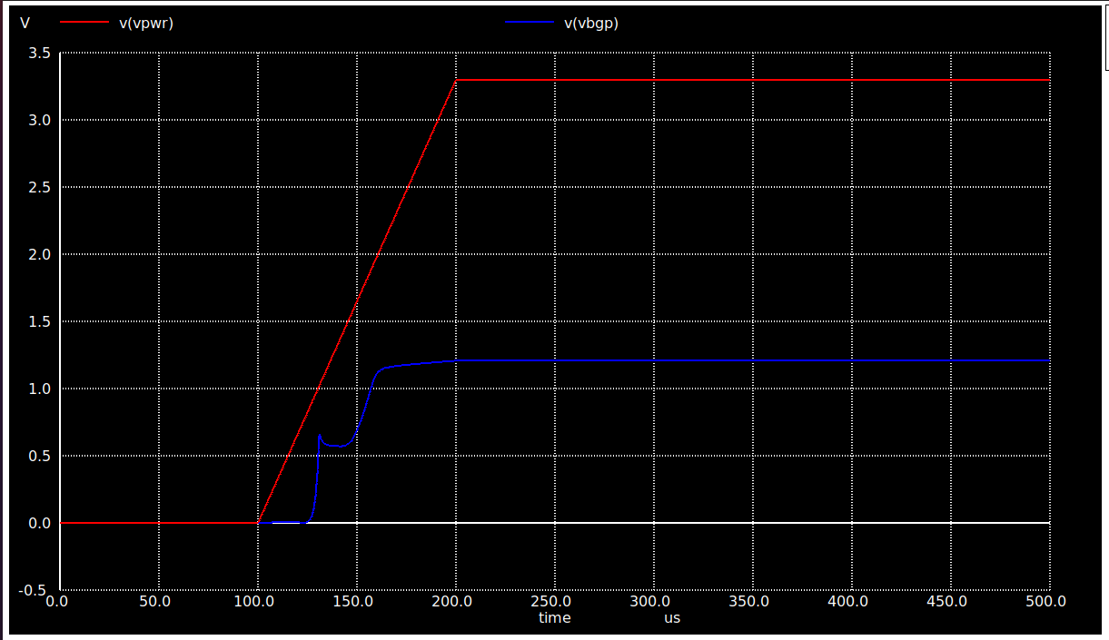
| ## Start-Up Time of Vbgp @ RL = 100M ohms plot |
| <p> </p> |
| On the terminal window, type :- |
| <p> </p> |
| |
| >`ngspice Start_up_avsdbgp_3v3.cir` |
| <p> </p> |
| The output plot as obtained can be seen below :- |
| <p> </p> |
| |
|  |
| <p> </p> |
| |
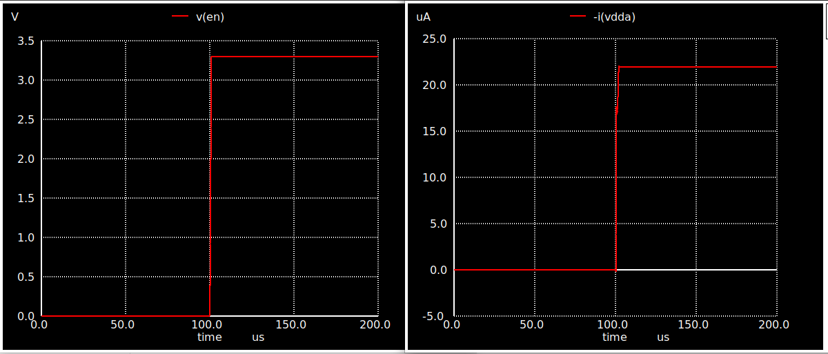
| ## On-Off-Current of Vbgp wrt Enable @ RL = 100M ohms plot |
| <p> </p> |
| On the terminal window, type :- |
| <p> </p> |
| |
| >`ngspice enable_current.cir` |
| <p> </p> |
| The output plot as obtained can be seen below :- |
| <p> </p> |
| |
|  |
| <p> </p> |
| |
| # BGR Layout |
| <p> </p> |
| |
| ## Magic |
| |
| The Layout for the circuit was done using Magic Layout editor tool. To observe the layout, install magic using the following commands :- |
| <p> </p> |
| |
| >`sudo wget "http://opencircuitdesign.com/magic/archive/magic-8.3.122.tgz" ` |
| |
| >`tar -xvzf magic-8.3.122.tgz` |
| |
| >` cd magic-8.3.122 ` |
| |
| >`sudo ./configure` |
| |
| >`sudo make` |
| |
| >`sudo make install` |
| <p> </p> |
| |
| ## Layout |
| |
| After successful installation, type:- |
| <p> </p> |
| |
| >`cd avsdbgp_3v3_sky130_v2/Layout/` |
| |
| >` magic -T ../libs/sky130A.tech BGR.mag` |
| <p> </p> |
| |
|  |
| <p> </p> |
| |
| # Post-Layout Simulation plots of Bandgap Reference IP circuit |
| <p> </p> |
| |
| To simulate the files for Post-Layout simulations using ngspice :- |
| |
| >`cd avsdbgp_3v3_sky130_v2/Post_Layout_Simulations/Circuits/` |
| <p> </p> |
| |
| ## Vbgp v/s Temperature [ -40C - 140C] @ RL = 100M ohms plot |
| <p> </p> |
| To observe the effect of temperature on the circuit, the temperature is varied from -40C to 140C. On the terminal window, type :- |
| <p> </p> |
| |
| >`ngspice temp_avsdbgp_3v3.spice` |
| <p> </p> |
| The output plot as obtained can be seen below :- |
| |
| <p> </p> |
| |
|  |
| <p> </p> |
| |
| |
|  |
| <p> </p> |
| |
| ## Vbgp v/s VDD [ 2V - 4V] @ RL = 100M ohms plot |
| <p> </p> |
| To observe the effect of Supply voltage on the circuit, the temperature is varied from 2V to 4V. On the terminal window, type :- |
| <p> </p> |
| |
| >`ngspice vdd_variation_avsdbgp_3v3.spice` |
| <p> </p> |
| The output plot as obtained can be seen below :- |
| <p> </p> |
| |
|  |
| <p> </p> |
| |
| ## Temperature Coefficient of Vbgp v/s Temperature [ -40C - 140C] @ RL = 100M ohms plot |
| <p> </p> |
| On the terminal window, type :- |
| <p> </p> |
| |
| >`ngspice Temp_coeff_avsdbgp_3v3.spice` |
| <p> </p> |
| The output plot as obtained can be seen below :- |
| <p> </p> |
| |
|  |
| <p> </p> |
| |
| ## Voltage Coefficient of Vbgp v/s VDD [ 2V - 4V] @ RL = 100M ohms plot |
| <p> </p> |
| On the terminal window, type :- |
| <p> </p> |
| |
| >`ngspice voltage_coeff_avsdbgp_3v3.spice` |
| <p> </p> |
| The output plot as obtained can be seen below :- |
| <p> </p> |
| |
|  |
| <p> </p> |
| |
| ## Start-Up Time of Vbgp @ RL = 100M ohms plot |
| <p> </p> |
| On the terminal window, type :- |
| <p> </p> |
| |
| >`ngspice Start_up_avsdbgp_3v3.spice` |
| <p> </p> |
| The output plot as obtained can be seen below :- |
| <p> </p> |
| |
|  |
| <p> </p> |
| |
| # Author |
| * [Anmol Purty](https://github.com/an3ol) |
| |
| # Acknowledgements |
| |
| * [Kunal Ghosh](https://github.com/kunalg123), Co-founder of VLSI System Design (VSD) Corp. Pvt. Ltd. |
| * [Tim Edwards](https://github.com/RTimothyEdwards), Senior Vice President of Analog and Design at efabless corporation. |
| * [Sheryl Corina Serrao](https://github.com/sherylcorina), Undergraduate Student, Mumbai University. |
| |
| # Contact Information |
| * Anmol Purty - nmlpurty@gmail.com |