Update README.md
diff --git a/README.md b/README.md
index 04e6885..1212bf4 100644
--- a/README.md
+++ b/README.md
@@ -66,7 +66,7 @@
The files from this repository can be downloaded and used by the following commands :-
>`sudo apt install -y git`
->`git clone https://github.com/an3ol/General-purpose-Bandgap-Reference-avsdbgp_3v3.git`
+>`git clone https://github.com/vsdip/avsdbgp_3v3_sky130_v2.git
<p> </p>
# Pre-Layout Simulation of Bandgap Reference IP circuit
@@ -94,7 +94,7 @@
To simulate the files for Pre- Layout simulations
<p> </p>
->`cd General-purpose-Bandgap-Reference-avsdbgp_3v3/Pre_Layout_Simulations/Circuits/`
+>`cd avsdbgp_3v3_sky130_v2/Pre_Layout_Simulations/Circuits/`
<p> </p>
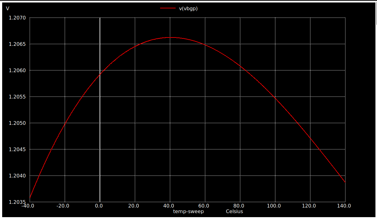
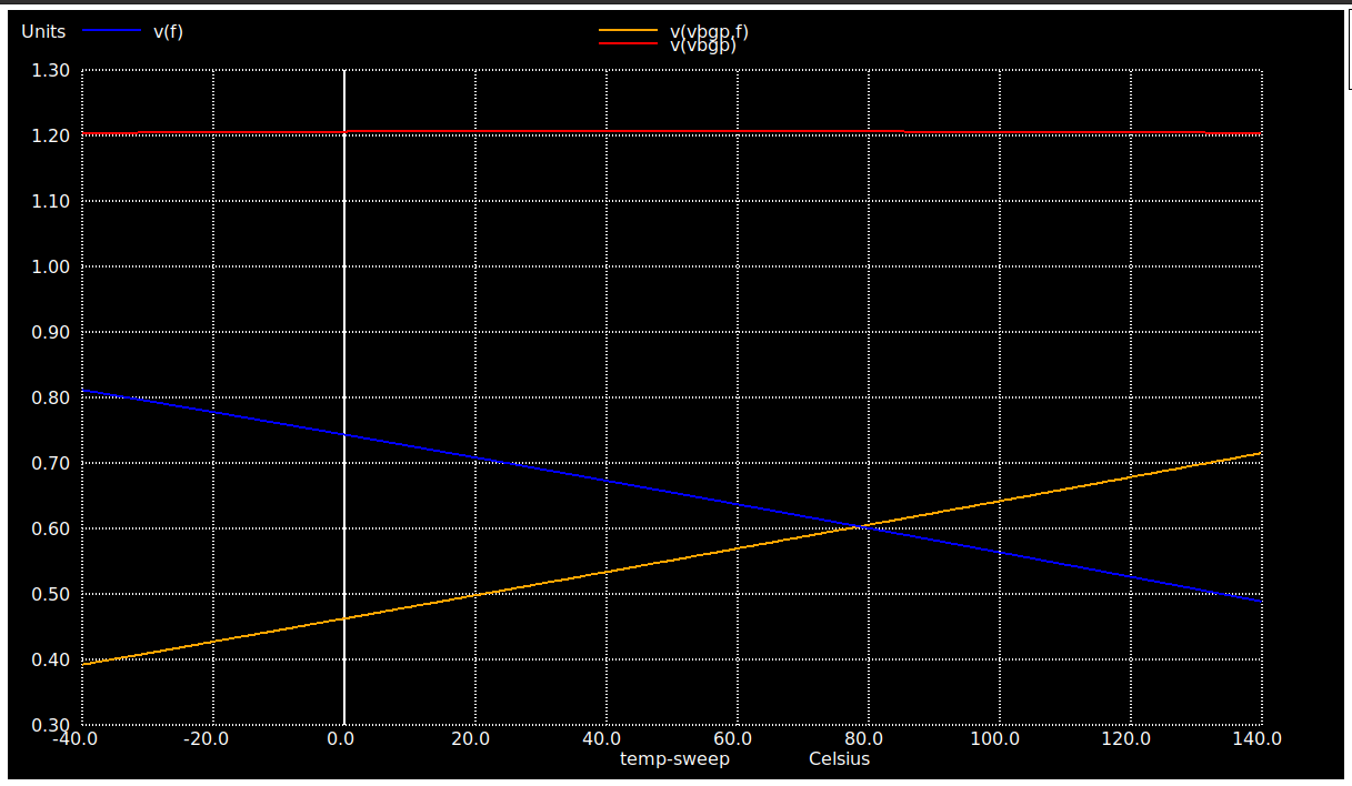
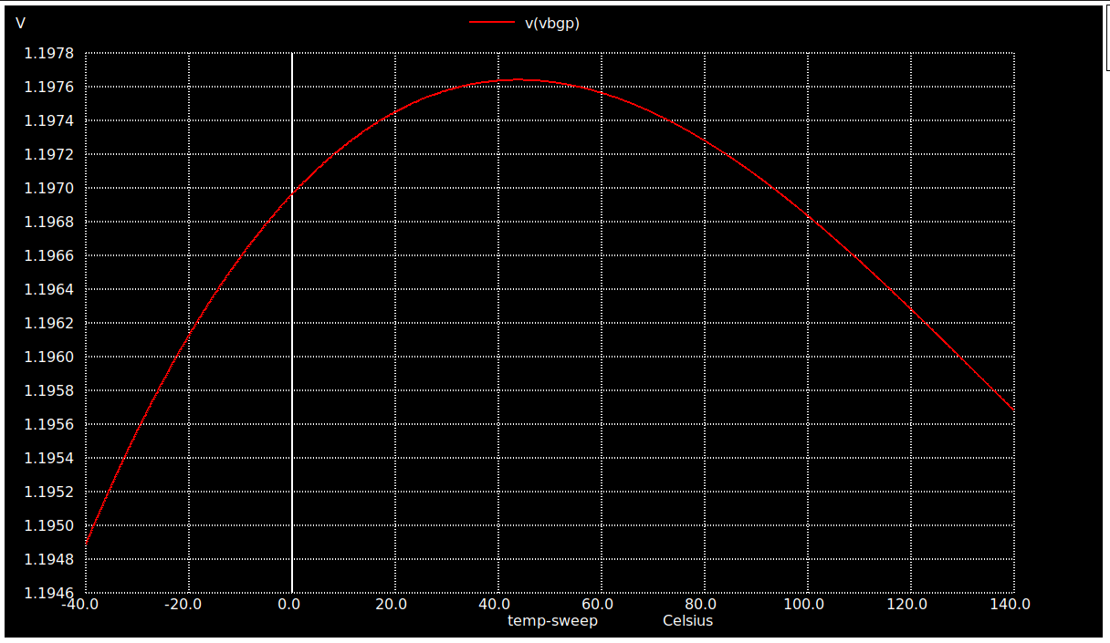
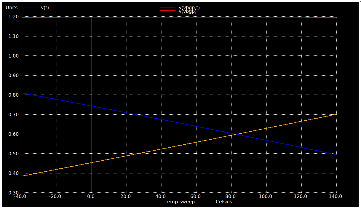
## Vbgp v/s Temperature [ -40C - 140C] @ RL = 100M ohms plot
@@ -108,11 +108,11 @@
<p> </p>
-
+
<p> </p>
-
+
<p> </p>
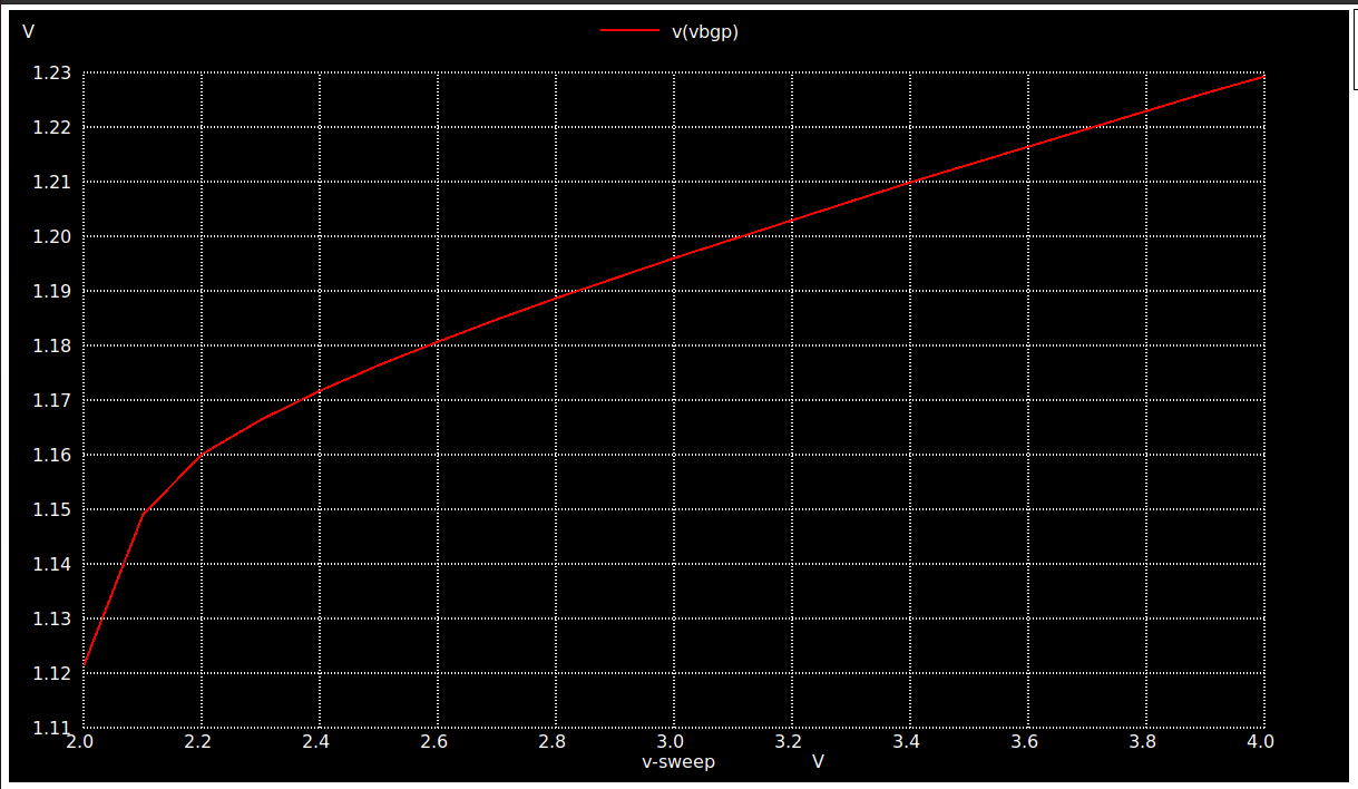
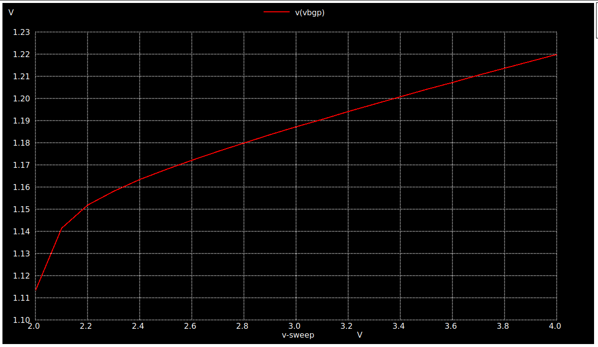
## Vbgp v/s VDD [ 2V - 4V] @ RL = 100M ohms plot
@@ -125,7 +125,7 @@
The output plot as obtained can be seen below :-
<p> </p>
-
+
<p> </p>
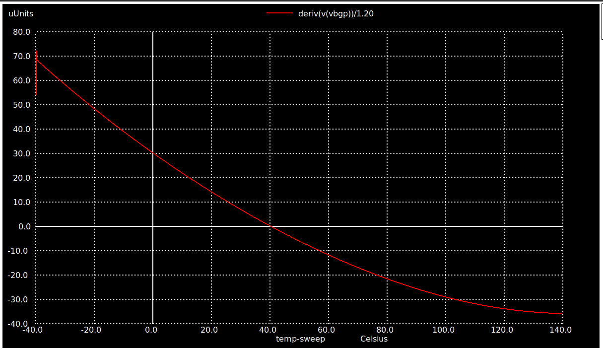
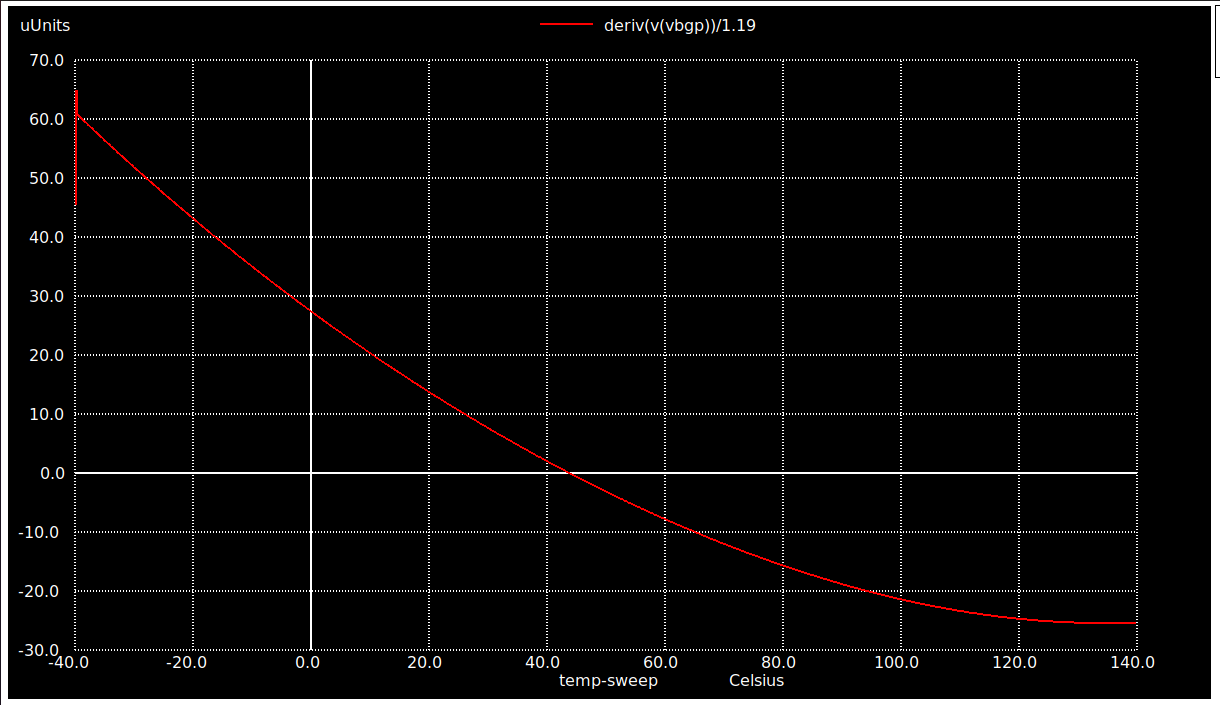
## Temperature Coefficient of Vbgp v/s Temperature [ -40C - 140C] @ RL = 100M ohms plot
@@ -138,7 +138,7 @@
The output plot as obtained can be seen below :-
<p> </p>
-
+
<p> </p>
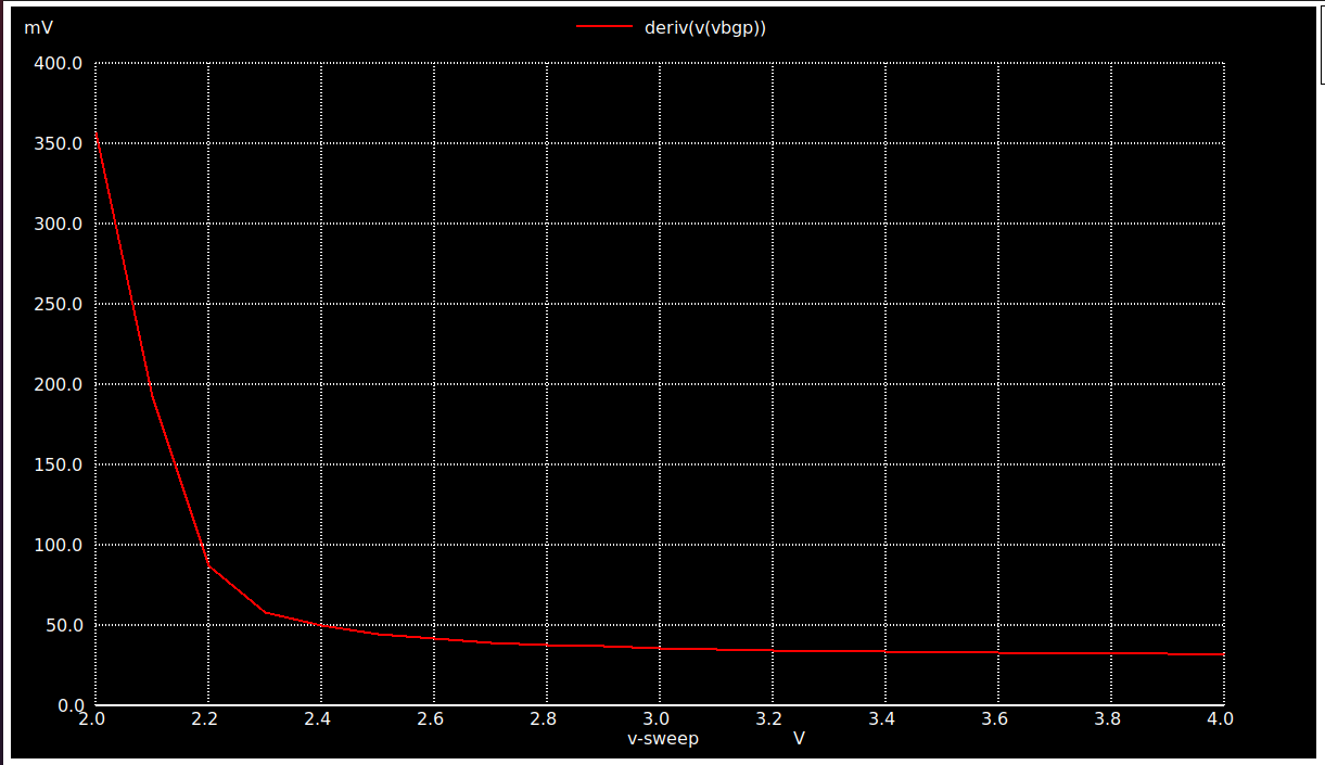
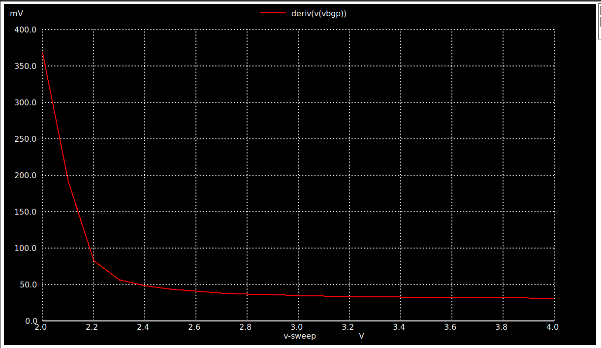
## Voltage Coefficient of Vbgp v/s VDD [ 2V - 4V] @ RL = 100M ohms plot
@@ -151,7 +151,7 @@
The output plot as obtained can be seen below :-
<p> </p>
-
+
<p> </p>
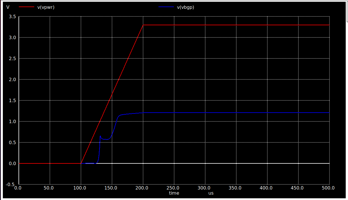
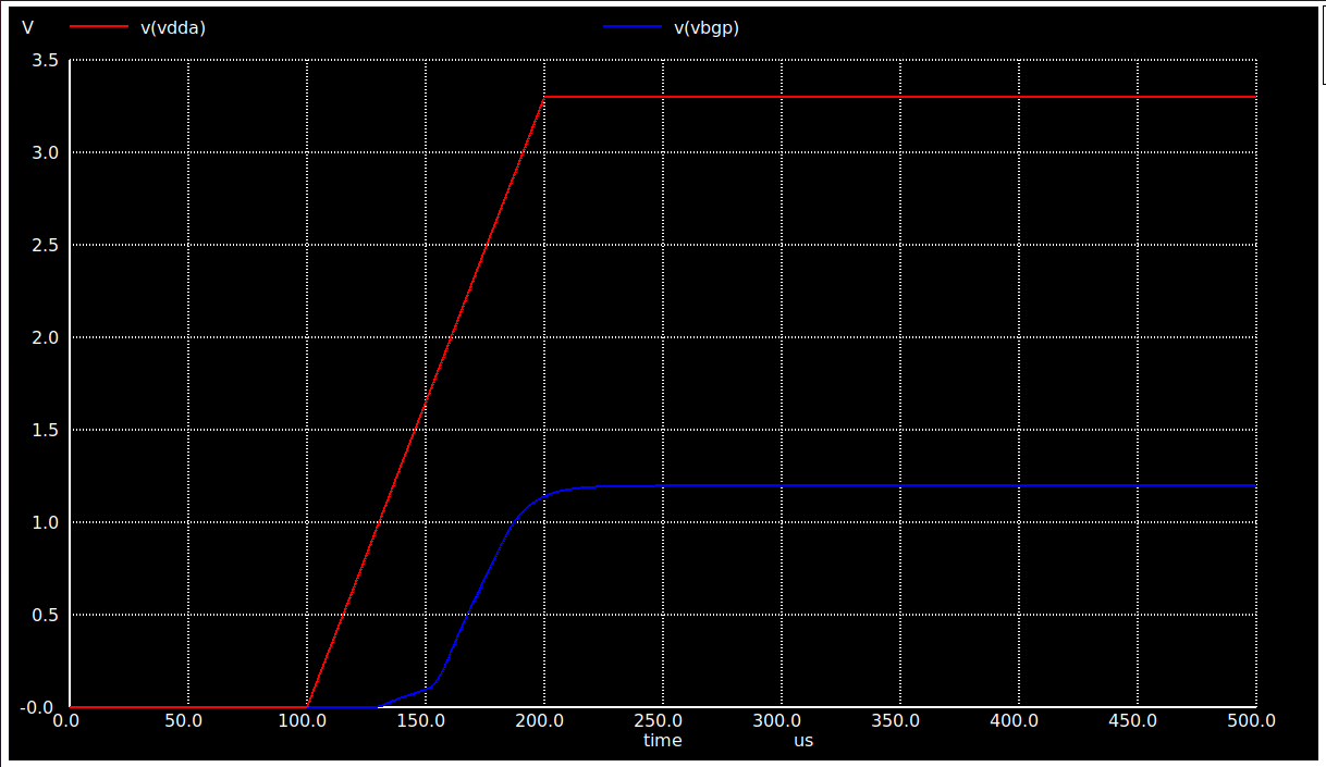
## Start-Up Time of Vbgp @ RL = 100M ohms plot
@@ -164,7 +164,7 @@
The output plot as obtained can be seen below :-
<p> </p>
-
+
<p> </p>
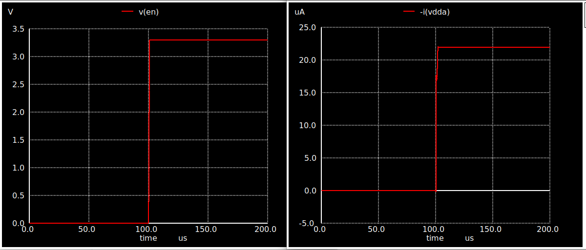
## On-Off-Current of Vbgp wrt Enable @ RL = 100M ohms plot
@@ -177,7 +177,7 @@
The output plot as obtained can be seen below :-
<p> </p>
-
+
<p> </p>
# BGR Layout
@@ -206,7 +206,7 @@
After successful installation, type:-
<p> </p>
->`cd General-purpose-Bandgap-Reference-avsdbgp_3v3/Layout/`
+>`cd avsdbgp_3v3_sky130_v2/Layout/`
>` magic -T ../libs/sky130A.tech BGR.mag`
<p> </p>
@@ -219,7 +219,7 @@
To simulate the files for Post-Layout simulations using ngspice :-
->`cd General-purpose-Bandgap-Reference-avsdbgp_3v3/Post_Layout_Simulations/Circuits/`
+>`cd avsdbgp_3v3_sky130_v2/Post_Layout_Simulations/Circuits/`
<p> </p>
## Vbgp v/s Temperature [ -40C - 140C] @ RL = 100M ohms plot
@@ -233,11 +233,11 @@
<p> </p>
-
+
<p> </p>
-
+
<p> </p>
## Vbgp v/s VDD [ 2V - 4V] @ RL = 100M ohms plot
@@ -250,7 +250,7 @@
The output plot as obtained can be seen below :-
<p> </p>
-
+
<p> </p>
## Temperature Coefficient of Vbgp v/s Temperature [ -40C - 140C] @ RL = 100M ohms plot
@@ -263,7 +263,7 @@
The output plot as obtained can be seen below :-
<p> </p>
-
+
<p> </p>
## Voltage Coefficient of Vbgp v/s VDD [ 2V - 4V] @ RL = 100M ohms plot
@@ -276,7 +276,7 @@
The output plot as obtained can be seen below :-
<p> </p>
-
+
<p> </p>
## Start-Up Time of Vbgp @ RL = 100M ohms plot
@@ -289,7 +289,7 @@
The output plot as obtained can be seen below :-
<p> </p>
-
+
<p> </p>